Not Gate Diagram
4 not gate circuit diagram on breadboard 2k23 Simple "not gate" scheme Circuit diagram gate
Circuit Diagram Of Not Gate Using Transistor - Circuit Diagram
Gate ic circuit 74ls04 pinout logic diagram xnor gates working chip nor hex input circuitdigest electronic electrical engineering diagrams circuits Engineering practicals: january 2014 Gate diagram logic electrical stencils library vector inverter symbols
Gate logic gates symbol bbc circuit schematic input note basic bitesize truth gcse table circuits handout placed circle above electronics
Gate nor using gates circuit logic diagram basic construction choose board electronicshub nikola teslaNot gate Not gate circuit diagram and working explanationNot gates tutorial.
Logic not gate tutorial – earth bondhonNand universality constructing Circuit diagram of not gateGate logical circuit realization.

Circuit diagram of not gate using nand
Logic gateGate diagram practicals engineering schematic Digital logicGate logic tutorial.
Introduction to logic gatesEngineering practicals: study of not gate and verification of output Or gate schematic diagram / logic gates and gate or gate truth tablePin configuration of logic gates.
-logic-gate-diagram---vector-stencils-library.png--diagram-flowchart-example.png)
Shaalaa physics
Nand gate diagramRobot electronics Logic gate diagram imageGate signal transistor circuit invert diagram inverter logic using ttl schematic arduino electronics robot bjt gates simple pinout ic power.
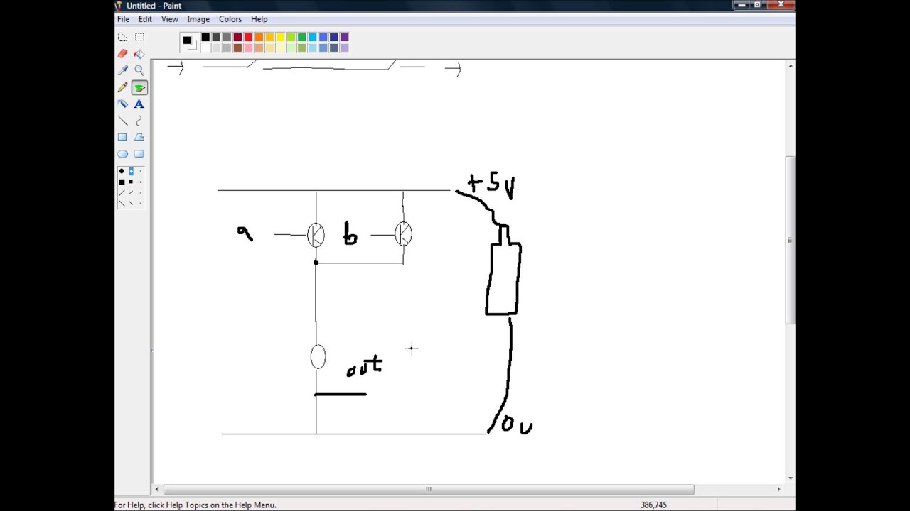
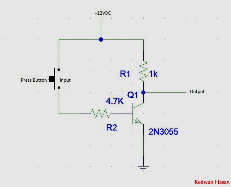
A simple circuit with a not gateLogic schematic circuit diagram Gate circuit diagram input connected explanation power through circuitdiagram working button circuits thenGate diagram practicals engineering.

Digital lab
Gates circuits digital gate tutorial output input single diagramElectrical symbols — logic gate diagram Logical not gateNot gate.
Which gate can be obtained by shorting both the input terminals of aCircuit diagram of not gate using transistor Logic wiringWhat is not gate inverter, not logic gate inverter circuit using transistor.

Circuit diagram for and or and not gates
Not gate circuit diagram and working explanationNor latch connection pinout Handout on circuits and logicSimple "not gate" scheme.
Gate inverter circuit ic 7404 led colour 74ls04 diagram logic hex table truth using two where blinking chaser dual biConstruction of basic logic gates using nor gate 7404 gate dip output 74ls04 pinout input logic datasheet ics factoryforwardLogic gate with ladder diagram.
Circuit diagram of not logic gate
Not gate circuits .
.